

High Strength Steel Welding FAQs
High strength steels continue to be popular for fabrication and manufacturing applications that require materials with less weight and thinner sections — without sacrificing strength. These include the building of cranes, Offshore Jack-up legs, heavy equipment, pressure vessels, bridges and more.
As with any material, high strength steels require special attention when it comes to welding. To help, here are answers to some frequently asked questions about the material and the process of welding it.
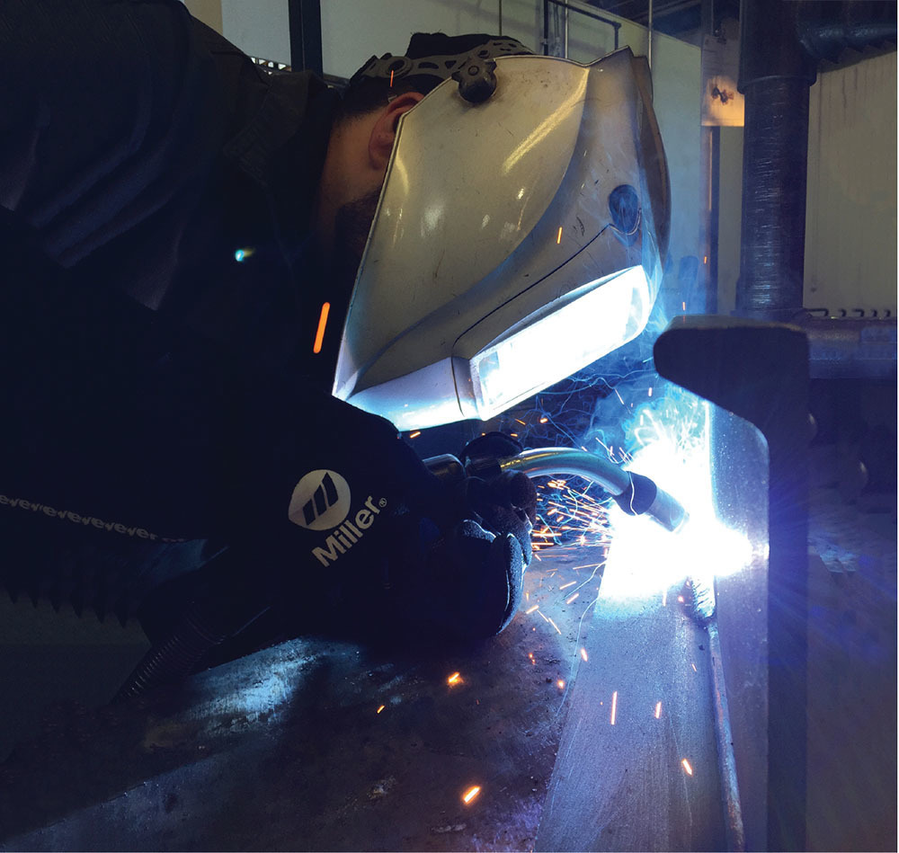
In addition to understanding the challenges of welding high strength steel and knowing the filler metal options for the job, it’s important to maintain awareness about controlling heat.
What is high strength steel?
High strength steel gains its strength from specific alloying elements, including manganese and nickel, as well as molybdenum and chromium, in some cases. This material has both high tensile and high yield strengths. Tensile strength refers to the amount of force required to bend the material until it breaks. Yield strength is the amount of force necessary to deform or bend the steel. Having higher levels of strength means that there is less chance of high strength materials breaking or deforming. Often this material is formulated according to industry standards and classified as EN, ASTM, ABS or AISI, but there are proprietary manufacturing processes too. For any formulation of high strength steel, it’s important to use a filler metal with the appropriate chemical and mechanical properties, especially since this material is designed to carry more and withstand more extreme service conditions.
What are the challenges of welding high strength steel?
Since high strength steel is often used in thinner sections, it reduces weight for the given application. However, it also can cause the material to shrink during the welding process, resulting in residual stress in the weld joint and greater risk of distortion. If the application requires multiple passes, placing smaller weld beads can help keep the heat input lower and reduce distortion. Keeping heat low also lessens the risk of weakening the material.
Cracking can also be an issue when welding high strength steel. For that reason, it’s important to control the amount of hydrogen being introduced into the weld. Low hydrogen filler metals are one line of defense. Controlling the cooling rate of the weld and material through proper preheat and the monitoring of interpass temperatures can also help reduce the opportunity for cracking.
What filler metals are best for the job?
Unlike more common materials like mild or carbon steel, there are fewer filler metal options for welding high strength steels. But like all materials, matching the mechanical strength of the filler metal with the high strength steel is key to maintaining weld integrity.
Low alloy metal-cored wires and low alloy gas-shielded flux-cored wires provide high tensile and yield strengths for welding high strength steels. The ELGA Filler Metals also contain low levels of hydrogen and carry a specific designator to indicate that. For example, an H4 designator according to AWS means that the wire has less than 4 milliliters of diffusible hydrogen per 100 grams of weldment.
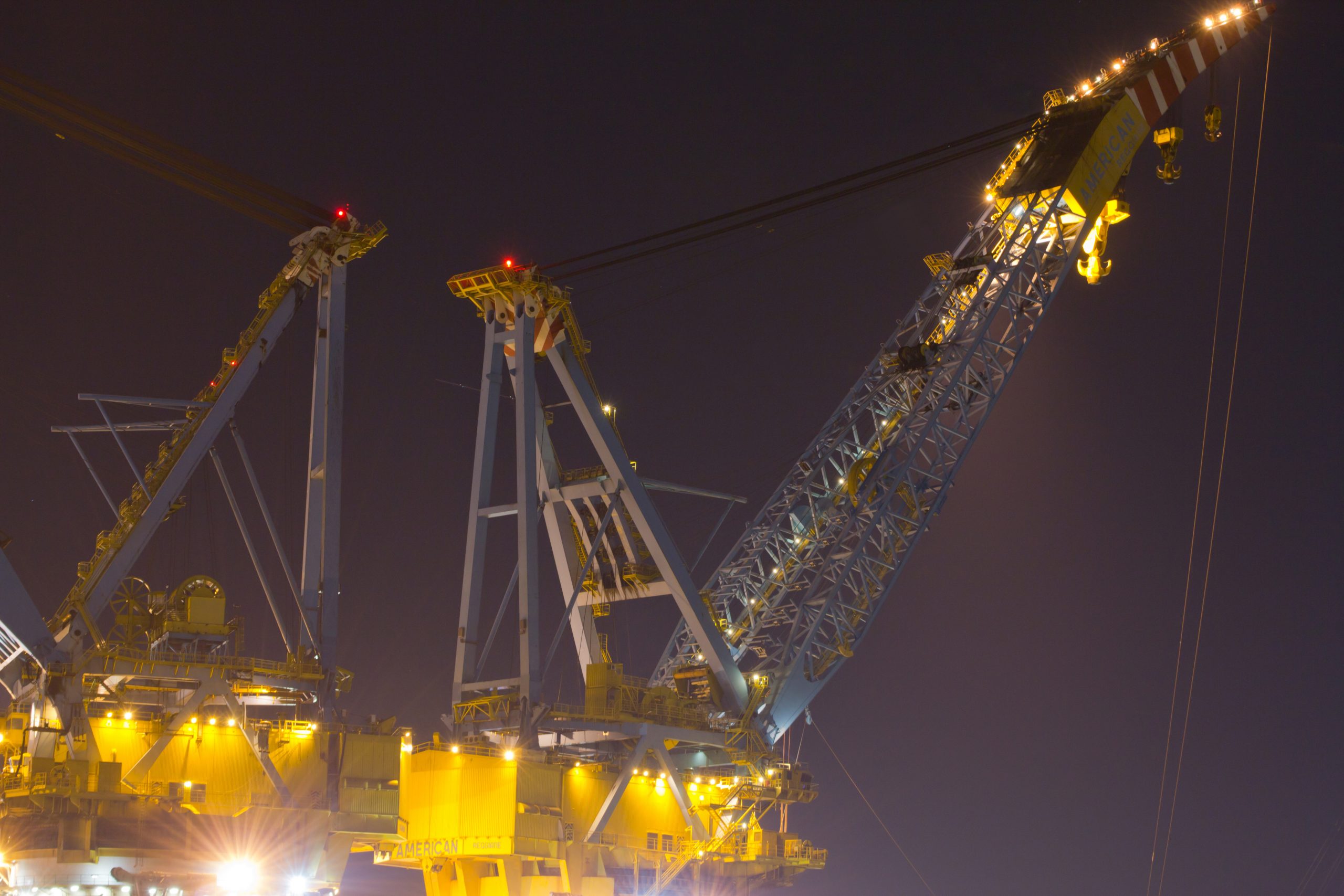
High strength steels continue to be popular for fabrication and manufacturing applications that require materials with less weight and thinner sections — without sacrificing strength. These include Cranes, heavy equipment, Offshore Jack up legs, etc.
ELGA offers a wide range of products for welding S690 or S890 grades. Metal-cored wires like MEGAFIL® 742 M or MEGAFIL® 1100 M are good choices for welding high strength steels. In the right application, they can offer higher deposition rates and travel speeds than other wires, leading to increased productivity. The ELGA High Strength Steels metal-cored wires also provide excellent toughness properties and very low hydrogen levels.
Options for welding high strength steel include gas-shielded flux-cored wires with either a Rutile (T-1) or Basic (T-5) slag system. All positional rutile (T-1) wires like MEGAFIL® 690 R offer good weldability and a stable arc; however, they tend to have slightly less ductility and toughness than Basic (T-5) wires. Conversely, wires with a basic slag system like MEGAFIL® 742 B offer good mechanical properties and strength, as well as low diffusible hydrogen levels. Unfortunately, Basic wires aren’t as operator friendly as Rutile wires and often generate more spatter. Depending on the application, these pros and cons will need to be weighed against one another. Like any other flux-cored wires, these wires require slag removal after welding or between passes.
Final thoughts
Preheating helps slow the cooling rate by keeping the temperature at the right level during welding, reducing cracking opportunity and helping the material regain toughness in and around the weld joint as it cools. Always check temperatures between passes to ensure they are in the proper range.
Adequate Cooling rate is key to obtain the required tensile strength and toughness and keep the hardness at the right level. Feel free to contact your ELGA representative for additional advice.