exclusion
2021-05-13

The Benefits of Metal-Cored Welding Wire

Metal-cored wire can bring key benefits to your welding operation compared to using solid wire — namely, improved productivity, higher weld quality, and lower costs.

  1. With the same welding wire size at the same operating parameters (amperage), metal-cored wire typically has a higher deposition rate, resulting in faster travel speeds for the same size weld.
  2. Metal-cored wire welds have higher tolerance for mill scale, oil, and dirt on the base material, often meaning that cleaning operations can be avoided. This helps manufacturers reduce labor costs and optimize productivity.
  3. The wire produces minimal spatter, so there is no need to apply anti-spatter and you can reduce post-weld grinding and cleanup.
  4. By eliminating pre- and post-weld activities, you can reallocate labor to other areas of your welding operation where welders can help increase throughput.
  5. Metal-cored wire provides good gap bridging and weld fusion to reduce the need for rework.
  6. Metal-cored wire is easy to use, so it can simplify training for new welders. The welding technique is very similar to solid wires.

Overall, metal-cored wire produces high weld quality and can yield up to a 30 percent increase in productivity. Faster cycle times mean you can get more parts out the door and gain a better bottom line.

2021-05-13

Is Metal-Cored Welding Wire Right for You?

In the right welding operation, metal-cored wire can provide process improvements and simplify training, particularly if you have less-skilled welders.

Metal-cored welding wire is a composite tubular wire that consists of a metal sheath with a core of metallic powders and alloys. In many situations, this wire can increase your welding efficiencies and reduce overall costs compared to solid wires.

When should metal-cored wire be used?

Metal-cored wire is especially effective when used in heavy equipment, automotive, and general manufacturing applications, and is a good alternative to solid wire when welding 3- to 6-mm thick mild steel.

It can also help if you are experiencing challenges in your welding operation, such as:

  1. Poor fit-up, gaps or burn-through issues
  2. Inadequate side wall fusion
  3. High levels of scrap or rework
  4. Excessive time and money for pre- and post-weld cleaning
  5. Slow new welder training

To decide if metal-cored wire is right for you, it’s important to understand how the technology works and the key benefits it can provide.

2021-05-13

How to Convert to Metal-Cored Welding Wire

Cost is always a factor when making a decision about your welding operation. Fortunately, the cost to change from solid wire to metal-cored wire is generally minimal — especially if you factor in the labor savings and increased productivity you can gain.

There are a four key steps to the process.

  1. Welding operation study.  Your filler metal provider can study your operation on-site or recreate the part production in its lab using solid wire and metal-cored wire — comparing the difference in travel speed, deposition rates and the time to complete the part.  From there, the provider can prorate the welding cost savings using metal-cored wire on per-shift, monthly or yearly basis.
  2. In-house trial. After reviewing the metal-cored wire data, you can trial the wire in a single welding cell, working with a filler metal specialist to optimize the parameters. Trials may run for a day, week, or even a month based on your preference.
  3. Potential welding procedure requalification. You may need to requalify your welding procedure for use with metal-cored wires, and it may be possible to conduct the testing in-house. If you require additional mechanical property testing, you can work with a third-party testing lab to ensure that your choice of metal-cored wire is qualified to your application.
  4. Conversion. Metal-cored wire can be implemented by changing over one cell or a group of cells at a time or during routine weld cell maintenance.

As with any change in the welding process, converting to metal-cored wire takes careful consideration. Consult with a trusted filler metal manufacturer or distributor to help with the process.

2021-05-13

MIG Troubleshooting for Metal-Cored and Solid Wire

MIG Troubleshooting for Metal-Cored and Solid Wire

MIG welding (also known as GMAW) is a popular process because of the productivity, reliability and ease of use it offers. However, issues can arise if a welder doesn’t use proper technique and parameters or perform proper equipment setup and maintenance. To help reduce lost productivity and downtime costs, it’s important to know how to quickly identify and solve issues like porosity, undercut, excessive spatter and more. Here are tips to identify and correct problems associated with using both metal-cored wire and solid wire in the MIG welding process.

Issue 1: Porosity

The most common cause of porosity when MIG welding is poor shielding of the weld pool, leading to contamination by atmospheric gases. Poor shielding occurs when the shielding gas flow is restricted, turbulent or insufficient.

Environmental factors such as wind can displace gas flow. It is best to relocate to an area with less wind, but screens can be used if they can reduce wind velocity in the welding area to 8 kilometers per hour (kph) at most.

Spatter buildup in the nozzle can also cause a turbulent or restricted flow. Be sure to periodically check the nozzle for excessive spatter buildup; if present, remove this buildup with welder’s pliers. While the nozzle is removed for cleaning, ensure that the diffuser’s gas ports are unobstructed.

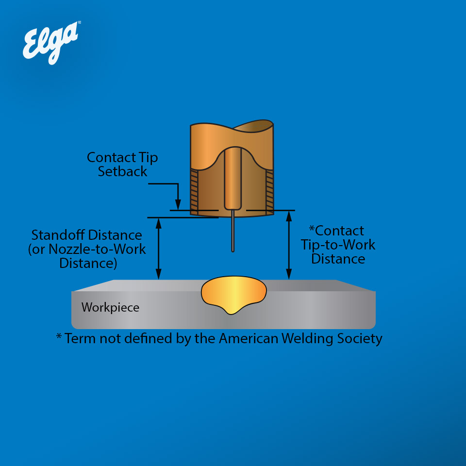
An insufficient flow typically results from setting the shielding gas flow meter incorrectly or using too small of a welding nozzle diameter for the weld pool being created. A flow rate of 15 to 22 l/min is often recommended when welding using a spray transfer. Welds that use higher amperages may require a higher flow rate. Be aware that excessive flow rates (especially relative to the nozzle diameter being used) and nozzle obstructions can lead to turbulence, which can introduce atmospheric gases into the shielding gas column.

Closeup of porosity on a welded steel welding coupon
Base metal contamination with oil, grease, mill
scale, rust or moisture can lead to welding porosity.
While metal-cored wire better tolerates base metal
contamination than solid wire does, it’s still important
to properly clean the material before welding.

When using solid wire with a short-circuit transfer process, welders can use lower flow rates — approximately 12 to 15 l/min — and still adequately shield the weld. The lower voltages and amperages of the short circuit transfer produce smaller weld pools that require less shielding gas to protect them from the atmosphere.

Base metal contamination with oil, grease, mill scale, rust and/or moisture can also lead to welding porosity. While metal-cored wire often better tolerates base metal contamination than solid wire does, it’s still important to properly clean the material of excessive contaminants before welding. Remember to store welding wires in a clean, dry place with a temperature similar to the welding environment; doing so minimizes the risk of condensation that can contaminate the material.

Issue 2: Undercut

Undercut can be created when the welder focuses the arc too much on the bottom plate and not enough on the top plate of the weld joint — in other words, when the welder uses an incorrect gun angle. Other common causes are excessive voltage and travel speeds that are too fast without using enough filler metal. If undercut is happening toward the end of the joints, arc blow (or arc wander) may be the cause.

Voltage influences arc force. When voltage is too high, it can cause the arc to want to push the molten weld pool out of the way. It also results in a more fluid pool with less surface tension that helps fight the pull of gravity to maintain an appropriate bead shape. Reducing the travel speed and increasing wire feed speed to ensure there is sufficient wire to fill the joint and areas gouged by the arc can help combat undercut. Pausing longer at each side of the weld bead when using a weave technique can also help.

To reduce the effects of arc blow, try moving the work lead clamp (often called the ground) to a different spot.

Issue 3: Weld spatter

A short-circuit transfer will always create higher spatter levels than a spray transfer. To generate minimal spatter levels and achieve maximum travel speeds, use sufficiently high voltages and wire feed speeds to obtain a spray transfer whenever possible. A voltage that is too low in relation to the wire feed speed is the most common contributor to excessive spatter levels, regardless of the transfer being used. Ideally, voltage should be high enough to minimize spatter, but not so high as to cause undercut.

Side view of welder welding part on a table with a power source nearby
The MIG welding process — whether it uses solid wire
or metal-cored wire — can be prone to common pitfalls.
To help reduce the downtime and costs associated with
troubleshooting, it’s important to know how to quickly
identify and solve issues.

MIG welding can tolerate some degree of base metal contaminants (particularly when using metal-cored wire) but the presence of base metal rust or mill scale increases the amount of spatter generated in addition to increasing the risk of porosity. Minimizing spatter is a matter of balancing the acceptable level against the time spent cleaning the base metal.

Spatter levels can also be influenced by shielding gas and wire selection. A 75% argon/25% carbon dioxide gas mixture typically results in less consistent transfer that generates more spatter than a 90% argon/10% carbon dioxide mixture. All other things being equal, metal-cored wire generally has a smoother arc that produces less spatter than solid wire.

An uncontrollable, erratic arc that generates high amounts of spatter repeatedly in one area of the weld/part is a typical symptom of arc blow. It can often be corrected by moving the work clamp or changing travel direction with respect to the work lead clamp.

Issue 4: Lack of fusion and poor penetration

Metal-cored wire typically provides a wider penetration profile than solid wire, making it easier to achieve fusion into the side walls of the weld and avoid lack of fusion in these areas. However, issues can still arise if the welding procedure and technique used are not optimized.

Welding current that is too low is the most common cause of lack of fusion. The amperages required to run a spray transfer mode with MIG welding typically help prevent lack of fusion. Stay out of the globular and short-circuit transfer ranges, which do not offer significant penetration.

„Riding the pool“ may be a cause, too. This happens when travel speed is too low for the wire feed speed and voltage selected so that the weld pool forms and/or flows significantly ahead of the wire. To prevent the issue, stay on the leading edge of the weld pool to maximize penetration and sidewall fusion. To stay on the leading edge without changing travel speed, reduce the wire feed speed. Conversely, to stay on the leading edge without changing the wire feed speed, increase the travel speed.

Running too small of a wire diameter can be another cause of fusion or penetration issues. Smaller wire diameters typically form narrower arc cones that may be too narrow and unable to spread out the molten filler metal. Larger diameter wires have lower deposition rates for the same amperage compared to smaller diameter wires, but offer a wider arc cone that assists fusion into the sidewalls. Larger diameter wires also allow welders to weld at higher currents with good arc stability; this is helpful if the current can no longer be increased while maintaining good weld quality when using a smaller diameter wire.

Welder technique and travel angle can also affect weld fusion. With solid and metal-cored wires, a push angle is typically used, but an excessive push angle can reduce penetration. Poor penetration in MIG welding can also be caused by joint design. It can help to open up the bevel angles of the joint or use a wider root opening.

Remember to store welding wires in a clean, dry place
with a temperature similar to the welding environment;
doing so minimizes the risk of condensation that can
contaminate the material.

Issue 5: Overlapping (cold lap)

Overlapping, also called cold lap, happens when the filler metal doesn’t fuse into the base material at the weld toes.

As with many other welding defects, this problem is often the result of multiple simultaneous factors. Overlap may be caused by riding the weld pool while adding too much filler and having insufficient voltage to spread the weld pool to the appropriate width. This problem can be remedied by increasing voltage and travel speed and reducing wire feed speed. Remember, it’s important to always stay on the leading edge of the weld pool for optimum weld penetration and quality.

Proper angle can also help eliminate cold lap. Welders should be sure to distribute the arc cone equally between the two base plates of a weld joint, assuming there is equal material thickness. One benefit of metal-cored wire is that the wider arc cone helps spread the weld metal out, so it’s more forgiving to variations in work angle than solid wire, which can help minimize the risk of cold lap.

Issue 6: Weld cracking

Both metal-cored and solid wires generally have low hydrogen levels and are resistant to moisture pickup that can contribute to hydrogen-induced weld cracking. However, cracked welds can be caused by numerous other factors, too. These include insufficient weld size, excessive joint restraint, poor joint design or a rapid weld cooling rate. Cracked welds can also result when the filler metal chemical composition is incompatible with the base material or the tensile strength and ductility of the filler metal doesn’t match the base metal or the application demands.

Adjustments can be made to weld procedures to obtain higher weld ductility and help prevent cracking. Shielding gas selection, for example, impacts ductility. Shielding gases with higher argon content (example: 90% argon/10% carbon dioxide) tend to offer smoother arc characteristics than lower argon shielding gas mixtures. They also tend to increase tensile strength, which can reduce weld metal ductility.

Addressing common MIG welding issues — whether porosity,
spatter or lack of fusion — can often be done with some
simple changes to joint design, welding technique or parameter
settings.

It is important to adjust the weld size to match the part thickness, reduce the weld cooling rate through the use of preheat, and reduce joint restraint through proper design. Very narrow, deep joints on thicker materials increase crack sensitivity, whether using solid wire or metal-cored wire.

Issue 7: Distortion

Welding distortion can be caused by many factors, but one likely culprit is part design or faulty joint preparation that requires additional weld volume. Making changes to design can help reduce distortion. For instance, instead of tack welding a 90-degree T joint, tack weld the parts slightly off square. This incorporates distortion during welding into the as-designed dimensions. Fitting the part to compensate for the distortion is often called presetting the joint. Intentionally bending parts before welding to compensate for distortion is often called precambering the joint.

Heat input is reduced when amperage and voltage are decreased and/or travel speed is increased. Minimizing heat input can help limit distortion. Metal-cored wire offers advantages over solid wire because it can provide a lower heat input (due to lower amperage) for the same wire feed speed.

MIG welding troubleshooting

Addressing common MIG welding issues — whether porosity, undercut, spatter or lack of fusion — can often be done with some simple changes to joint design, welding technique or parameter settings.

In addition, using metal-cored wire rather than solid wire in the right applications can deliver numerous benefits that help address some of these basic MIG welding problems. In either case, knowing how to quickly identify and solve problems can help keep the welding operation on track — in terms of quality, productivity and costs.

2021-05-13

What Are Stickout, Electrode Extension and Contact-Tip-To-Work Distance?

What Are Stickout, Electrode Extension and Contact-Tip-To-Work Distance?

Stickout and electrode extension are often used interchangeably. Learn more about the difference and how it impacts weld quality.

Understanding welding terms

Producing quality welds requires attention to detail in setting weld parameters. Even slight changes can lead to significantly different results.

Achieving the right parameters to get the results you want requires understanding and using proper welding terms. Here’s an example I see frequently across the industry: People often use electrode extension, stickout and contact-tip-to-work distance interchangeably.

But these terms measure different things, and using them interchangeably — or not understanding their proper meanings — can cause confusion that alters weld parameters and, ultimately, weld quality.

So, how do electrode extension, stickout and contact-tip-to-work distance differ? Let’s talk about each one and why it’s important to use the proper term.


Understanding the difference

Changing the distance between your welding gun and the workpiece affects the amount of resistance in the welding circuit, and a change to the resistance also alters amperage in a constant voltage process like gas metal arc welding (GMAW). To help ensure and maintain proper amperage in your application, it’s important to know the meaning of these common terms and how they differ:


  • Electrode extension: As defined by the American Welding Society (AWS), this refers to the length from the end of the contact tip to where the wire melts off.
  • Stickout: Another common term defined by the AWS, this refers to the end of the nozzle to where the wire melts off. The only time that electrode extension and stickout can be used interchangeably is when the contact tip is flush with the end of the nozzle. In instances where the contact tip is recessed, these two terms refer to different distances.
  • Contact-tip-to-work distance: While this is a commonly used industry term — even in many weld procedures — it’s not actually defined by AWS A3.0 Standard terms and definitions. The best time to measure contact-tip-to-work distance is when you’re preparing the weld or programming the robot, and you can take a physical measurement before you strike the arc. Once the arc is struck, arc length is measured by voltage, and electrode extension can be measured by resistance in the circuit or with sight. When people use the term contact-tip-to-work distance, they often mean the sum of arc length and electrode extension.

How it affects amperage

Maintaining consistent electrode extension during welding is critical because varying the extension can change your amperage, which can put you out of range of your welding specifications. When that happens, you may be depositing a weld that’s less than sound.

Too short of an electrode extension increases the amperage and brings you closer to the weld pool, which can cause premature damage to the contact tip and create burn-through from too much heat. Too much extension lowers the amperage and can result in poor penetration that requires rework.


Consider this example of GMAW in spray transfer mode using the same wire type, shielding gas, base metal and nozzle diameter in both instances. The original contact-tip-to-work distance was 19mm, resulting in 235 amperes. With nothing else changing except the contact-tip-to-work distance, simply changing that from 16mm to 25mm causes amperage to operate in a window from 282 to 213 — which could put you out of spec for the application.

This happens because increasing the distance causes an increase in resistance — and the amount of resistance in the welding circuit can make or break your weld quality. To see just how much even small changes to this distance can affect amperage, you can play around with changing the electrode extension in your noncritical welding applications.


Improve weld quality

Contact-tip-to-work distance is often the most logical term to use in welding applications. But it’s important to know that electrode extension, stickout and contact-tip-to-work distance all have specific definitions, and using them interchangeably can cause confusion that puts amperage out of the specified range.

It’s especially important to use the right industry standard terms when communicating globally about welding applications — to help ensure that all parties are on the same page.

The bottom line: Understanding the terms being used provides clarity that can help prevent mistakes and rework.


2021-05-13

High Strength Steel Welding FAQs

High strength steels continue to be popular for fabrication and manufacturing applications that require materials with less weight and thinner sections — without sacrificing strength. These include the building of cranes, Offshore Jack-up legs, heavy equipment, pressure vessels, bridges and more.

As with any material, high strength steels require special attention when it comes to welding. To help, here are answers to some frequently asked questions about the material and the process of welding it.


In addition to understanding the challenges of welding high strength steel and knowing the filler metal options for the job, it’s important to maintain awareness about controlling heat.


What is high strength steel?

High strength steel gains its strength from specific alloying elements, including manganese and nickel, as well as molybdenum and chromium, in some cases. This material has both high tensile and high yield strengths. Tensile strength refers to the amount of force required to bend the material until it breaks. Yield strength is the amount of force necessary to deform or bend the steel. Having higher levels of strength means that there is less chance of high strength materials breaking or deforming. Often this material is formulated according to industry standards and classified as EN, ASTM, ABS or AISI, but there are proprietary manufacturing processes too. For any formulation of high strength steel, it’s important to use a filler metal with the appropriate chemical and mechanical properties, especially since this material is designed to carry more and withstand more extreme service conditions.


What are the challenges of welding high strength steel?

Since high strength steel is often used in thinner sections, it reduces weight for the given application. However, it also can cause the material to shrink during the welding process, resulting in residual stress in the weld joint and greater risk of distortion. If the application requires multiple passes, placing smaller weld beads can help keep the heat input lower and reduce distortion. Keeping heat low also lessens the risk of weakening the material.

Cracking can also be an issue when welding high strength steel. For that reason, it’s important to control the amount of hydrogen being introduced into the weld. Low hydrogen filler metals are one line of defense. Controlling the cooling rate of the weld and material through proper preheat and the monitoring of interpass temperatures can also help reduce the opportunity for cracking.


What filler metals are best for the job?

Unlike more common materials like mild or carbon steel, there are fewer filler metal options for welding high strength steels. But like all materials, matching the mechanical strength of the filler metal with the high strength steel is key to maintaining weld integrity.

Low alloy metal-cored wires and low alloy gas-shielded flux-cored wires provide high tensile and yield strengths for welding high strength steels. The ELGA Filler Metals also contain low levels of hydrogen and carry a specific designator to indicate that. For example, an H4 designator according to AWS means that the wire has less than 4 milliliters of diffusible hydrogen per 100 grams of weldment.

High strength steels continue to be popular for fabrication and manufacturing applications that require materials with less weight and thinner sections — without sacrificing strength. These include Cranes, heavy equipment, Offshore Jack up legs, etc.

ELGA offers a wide range of products for welding S690 or S890 grades. Metal-cored wires like MEGAFIL® 742 M or MEGAFIL® 1100 M are good choices for welding high strength steels. In the right application, they can offer higher deposition rates and travel speeds than other wires, leading to increased productivity. The ELGA High Strength Steels metal-cored wires also provide excellent toughness properties and very low hydrogen levels.

Options for welding high strength steel include gas-shielded flux-cored wires with either a Rutile (T-1) or Basic (T-5) slag system. All positional rutile (T-1) wires like MEGAFIL® 690 R offer good weldability and a stable arc; however, they tend to have slightly less ductility and toughness than Basic (T-5) wires. Conversely, wires with a basic slag system like MEGAFIL® 742 B offer good mechanical properties and strength, as well as low diffusible hydrogen levels. Unfortunately, Basic wires aren’t as operator friendly as Rutile wires and often generate more spatter. Depending on the application, these pros and cons will need to be weighed against one another. Like any other flux-cored wires, these wires require slag removal after welding or between passes.


Final thoughts

Preheating helps slow the cooling rate by keeping the temperature at the right level during welding, reducing cracking opportunity and helping the material regain toughness in and around the weld joint as it cools. Always check temperatures between passes to ensure they are in the proper range.

Adequate Cooling rate is key to obtain the required tensile strength and toughness and keep the hardness at the right level. Feel free to contact your ELGA representative for additional advice.